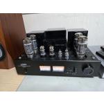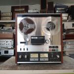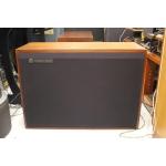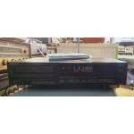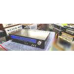
Tektronix 764 디지털 오디오 모니터 digital audio analyzer
작동정상 중고제품
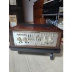
랙케이스에 장착된 상태에서 탈거한 제품이라 겉 케이스가 없습니다
(실사진참조)
정상 사용하든 제품으로 기능엔 하자 없습니다.
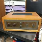
그리고 실사에서 보이는 것 처럼 볼륨조절손잡이가 하나 부러졌습니다.
CRT화면상태도 좋습니다.
전원 AC220V 전원케이블 포함
뒷쪽에 VGA 단자가 있는걸로 보니 PC용 모니터로도 출력이 되나봅니다.
Dimensions | cm | in. |
|---|---|---|
Weight | kg | lb. |
Height | 13.3 | 5.25 |
Width | 21.6 | 8.5 |
Depth | 43.2 | 17 |
| 4.5kg | 10 |
발매당시 신품가는 $5,000 - $7,000
판매가 인하 택포 40만 무료배송(우체국택배 안전포장) 직거래(창원)
>> 공일일-577-2497
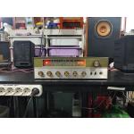
방송국에서 사용하든 전문 장비입니다만
전문가수준의 음향기기 매니어분이나
수리하시는 분에게도 유용할 것 같아서 올려봅니다.
잘은 모르지만 시중에 그리 흔하게 나오는 계측기는 아닌 것 같습니다.
EnJoyAV의 네이버 블로그 구경하기 --> https://blog.naver.com/ditcman
M** 방송국 입고년도는 2000년입니다.
https://kenrockwell.com/audio/tek/764.htm
https://www.tek.com/764-software/764-software-upgrade
https://kr.tek.com/764-manual/764-service-manual
https://www.tek.com/datasheet/764-digital-audio-monitor
Features and Benefits
- Two Balanced or Unbalanced AES/EBU or SPDIF Loopthrough Inputs Drive Four-channel Level Meters
- Adjustable Clip/Mute Indicators
- Audio Phase Display
- Phase Correlation Meter
- Unique Session Statistics Compilation
- VITC and LTC Time Code Inputs
- Channel Status and User Data Decoding
- AES-3 DARS Input
Characteristics
Digital Audio Inputs 1/2, 3/4
Connector
XLR conforming to AES3-1992 and EBU 3250-E.
BNC conforming to AES3-ID.
Signal format
Balanced, 24 data bits, 4 preamble bits, C, U, V and P bits.
MIN
TYP
MAX
UNITS
Voltage range
XLR
0.2
10
Vp-p
BNC
0.05
2
Vp-p
Impedance (0.1 to 6 MHz)
XLR termination switched in
104.5
110
115.5
Ω
Return loss (0.1 to 6 MHz)
XLR termination switched out
25
dB
BNC
25
dB
Sample rate range
27
52
kHz
Digital Audio Reference Input
Connector
XLR conforming to AES3-1992.
BNC conforming to AES3-ID.
Signal format
Balanced, 24 data bits ignored, 4 preamble bits, C, U, V and P bits.
MIN
TYP
MAX
UNITS
Voltage range
XLR
0.6
10
Vp-p
BNC
0.2
2
Vp-p
Impedance
XLR
104.5
110
115.5
Ω
BNC
71.25
75
78.75
Ω
Sample rate range
27
52
kHz
Vertical Interval Time Code Input
Connector
BNC, 75 Ω conforming to IEC461, NTSC and PAL specifications.
Signal format
Video with SMPTE VITC, 1 volt nominal.
Longitudinal Time Code Input
Connector
XLR.
Signal format
Reads SMPTE and EBU LTC.
Indicates time as hours:minutes:seconds.
MIN
TYP
MAX
UNITS
Voltage range
0.25
10
Vp-p
Impedance
5
kΩ
Level Meters
MIN
TYP
MAX
UNITS
Accuracy Error
Dynamic Response
Detectors
Range
-60
0
dBFS
True peak, 0 to -20 dBFS, steady tone
0.05
dB
Test level range
-30
0
dBFS
Peak program level range
-30
0
dBFS
True peak
Bar indicates true peak value (no attack delay). Bar decay is same for PPM.
PPM
Bar indicates quasi-peak value; conforms to IEC 268-10A & IEEE Std 152-1991.
VU
Bar has VU dynamic characteristic conforming to IEEE Std 152-1991.
Clip, sensitivity range
0
99
samples
Mute, sensitivity range
0
99
samples
Phase Display
MIN
TYP
MAX
UNITS
Automatic gain control range
-40
0
dBFS
Session Screen Display
MIN
TYP
MAX
UNITS
Clip counter range
999
events
Mute counter range
999
events
Invalid samples
999
events
Parity errors
999
events
Code violations
999
events
Active bits
24
bits
DC offset range
-90
dBFS
Sample Rate Measurement
MIN
TYP
MAX
UNITS
Range
27
52
kHz
Resolution
10
Hz
Accuracy
10
Hz
Synchronization Measurement
MIN
TYP
MAX
UNITS
Range
±50%
frame
±64
U.I.
Power Supply
MIN
TYP
MAX
UNITS
Input range
90
250
VAC
Input frequency
48
62
Hz
Consumption
56
65
Watts
Physical Characteristics
Dimensions
cm
in.
Weight
kg
lb.
Height
13.3
5.25
Width
21.6
8.5
Depth
43.2
17
4.5
10
Option 01 Embedded Audio Input Specifications
Serial Digital Video Input
Input Type - 75 Ω (nominal), BNC.
Serial Digital Video Formats Accepted - Audio embedded per SMPTE 272M level B in the following video formats: 270 Mb/s component digital (625- and 525-line) complying with SMPTE 259M and CCIR 656-1.
Input Level - 800 mVp-p ±10%.
Return Loss - ≥15 dB, power on.
Equalization Range - Proper operation with up to 19.0 dB loss at 135 MHz using coaxial cable having 1/f- loss characteristics with a launch amplitude of 800 mV.
Serial Digital Video Output
Output Type - 75 Ω (nominal), BNC, active loopthrough.
Output Level - 800 mV ±10%.
Return Loss - ≥15 dB.
Option 02 Analog Line Output Specifications
Output Type - Balanced XLRs (2 channels).
Output Impedance - 50 Ω, nominal.
Frequency Response, 20 Hz to 20 kHz - ±2 dB.
THD+N (20 Hz to 20 kHz, 22 kHz measurement bandwidth) - <0.05%.
THD+N (at 1 kHz, 22 kHz measurement bandwidth, fixed or variable (volume control fully CW) level outputs, 0 dBFS input, RL ≥10 kΩ) - typically <0.005%.
Output Levels (0 dBFS, RL = 600 Ω) - Fixed: 24 dBm.
Variable (volume control fully CW): 24 dBm.
Certifications and Compliance
EMC - Certified to the EMC Directive 89/336/EEC.
Safety - UL3111-1, ANSI/ISA S82.01, CAN/CSA C22.2 No. 1010.1, EN 61010-1.
- Optional Serial Digital Video (Embedded Audio) Input
- Optional Balanced Analog Line Outputs
- Supports a Pair of AES Streams Output by Professional DVTRs
- Configurable Level Indicators Support a Variety of Technical Preferences
- Mono Compatibility and Sound-stage Monitoring Assured via Phase Display
- Clear Phase Indication Regardless of Signal Amplitude or Panning
- Quality Control Certificate via Session Statistics Compilation
- Time Code Stamping of Errors Pinpoints Audio Needing Correction
- Simple Viewing of Encoded Channel Status and User Data
- System Timing Measurements to Recognized Standard
- Monitor Embedded Audio Without an External Demultiplexer
- Monitor Sound via Loudspeakers Without External Converters
Applications
- Digital Audio Monitoring in Broadcast and Post Production Facilities
- Creative Adjustments in Digital Audio Production
The Tektronix 764 Digital Audio Monitor is an advanced monitoring tool for production and quality assessment in modern digital audio facilities. It combines the features of a phase and level meter with those of a digital audio data monitor. The 764 provides technical personnel with a setup and calibration tool and production personnel with an operational monitor capable of conventional and advanced audio assessment tasks.
The 764 is well equipped for these tasks. Easy-to-read display screens can be viewed from across a room. An auxiliary VGA output supports larger color display units. Its two AES/EBU input channels have loopthrough capability permitting the 764 to be assigned to any signal path. Operation follows an easy-to-use, menu-driven scheme.
Audio Level
Audio amplitude measurement results are displayed on up to four bar graphs. Most characteristics can be configured to user preferences. This includes the amplitude scale and ballistics, peak-hold characteristics and the value of test and peak levels. Other features include detection of digital clipping and muting and detection of system errors.
Audio Phase
A Lissajous display is augmented with a mathematical phase correlation meter. In addition, selectable Sum and Difference bars provide an additional phase assessment tool.
Time Code
The 764 features Time Code input and display capabilities. Vertical Interval and Longitudinal Time Code can be displayed for locating specific audio passages.
System Timing
A Digital Audio Reference input, conforming to AES recommendations, permits 764 users to assess timing relationships between digital audio signals. Common problems due to sample slipping and non-locked signals can easily be detected.
Status and User Data
Channel Status and User data are recovered and displayed in contiguous 24-byte blocks. This allows the content and format of these auxiliary data channels to be monitored.
Optional Embedded Audio Input
Embedded audio technology simplifies routing of video and audio signals in broadcast and post-production facilities, but places new demands on audio monitoring equipment. To eliminate the need for a separate digital audio demultiplexing step for signal monitoring, the Option 01 Embedded Audio Input adds a serial digital video input to the standard digital audio inputs of the 764. Once it extracts the digital audio signal, the 764 provides the same comprehensive monitoring capabilities as it does for discrete AES/EBU audio.
The 764's Embedded Audio Input option extracts digital audio from 270 Mb/s serial component signals and from 143 (525 line) Mb/s serial composite signals. Audio data up to 20 bits at a 48 kHz sample rate is supported.
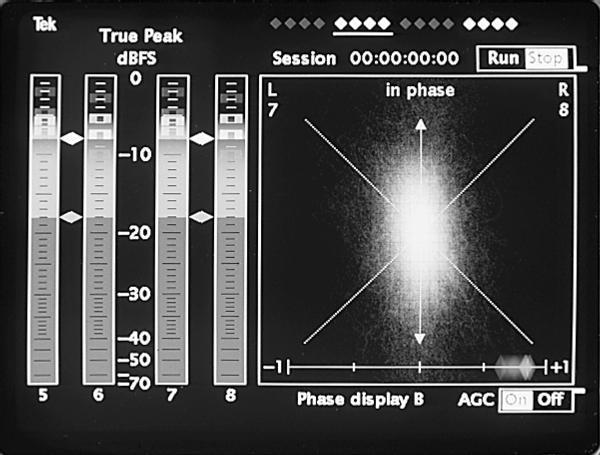
Figure 1. With the optional embedded audio input, active channels (white diamonds) and selected group (underline) are displayed at the top of the screen.
Figure 1 shows how the 764's Embedded Audio Input option indicates (for serial component video systems) which of the possible 16 audio channels are active (white diamonds) or inactive (gray diamonds) and indicates which group is selected for monitoring (underline). All channel numbers are reported appropriately on all displays.
Optional Analog Line Outputs
Many applications require listening over loudspeakers as a part of the audio monitoring process. In digital facilities, an audio feed is typically routed to a digital-to-analog converter, which drives an amplifier and speakers. Option 02 Analog Line Output provides the digital-to-analog conversion within the 764, eliminating the space requirements and expense of external conversion devices.
The balanced line output level can be either fixed or variable (via the headphone Volume control) and calibrated output level settings are selectable by internal jumpers. Jumper settings are also available for driving unbalanced loads at low levels. Rear-panel AES/EBU balanced output capability is lost when this option is installed.
Common Applications
- Consoles and workstations
- DAT, D1, D2, D3, etc.
- Digital STL for radio
- A/D testing and alignment
- Digital audio routers
- Signal processing
- Duplication and mastering
Monitoring audio level and phase
The "Audio" view of the 764 provides bar graph indicators for audio level and a combination Lissajous and phase correlation meter. In this configuration, the 764 supports on-line monitoring of audio level and phase for editing and mixing sessions, master control monitoring and equipment lineup activities.
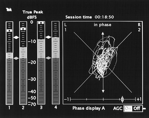
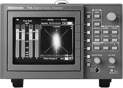
Figure 2. The 764 Audio View.
The four bar graphs illustrated in Figure 2 represent the program levels of two stereo AES channels. Indicators are provided for Peak Hold, Lineup or Test level and Peak Program level. The 764 warns of clipping and muting with on-screen flags.
Many characteristics of the level metering subsystem are user-selectable. Some of the choices include: VU, PPM and True Peak ballistics, variable scale resolution, offset range and user-configurable clipping and muting detector behavior. These settings can be saved as recallable setups.
The graphical phase display illustrated in Figure 2 is used to assess mono compatibility of the audio material as well as visualizing the stereo image or balance of the material. Experienced users of this type of display can easily detect the differences between mono signals, "pan-pot" stereo and true stereo signals.
The correlation meter, displayed directly below the graphical phase display, is purely a phase indicator. It immediately identifies inadvertent phase reversal errors that destroy stereo imaging. It provides an approximate indication of the Sum/Difference ratio of material destined to be broadcast via multiplexed transmission methods. An added dimension is the ability to substitute Sum and Difference bars for either the CH 1/2 or CH 3/4 program level bars.
Detecting Clipping and Muting
Perhaps the single most common operating problem in digital audio systems occurs when the input range of A/D converters is exceeded by signals whose amplitude is too large. It is important to detect this situation, known as "clipping" because it can degrade audio quality and introduce distortion artifacts. Figure 3 illustrates the on-screen indicator that signals when clipping is present.
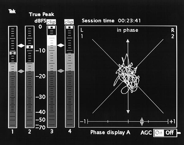
Figure 3. The 764 detects and displays digital clipping.
The behavior of the clipping detector can be modified according to the audio program material and preferences of the audio engineer. For example, if the mix and material demand that no full-scale samples be present in the media, then the trigger point for the clip indicator (and counter) can be set to its most sensitive position. At this point, just one full-scale sample will trigger the clip indicator. On the other hand, when some full-scale samples are permitted, the sensitivity of the clip detector can be reduced by specifying the number of consecutive full-scale samples that must occur before the clipping detector is triggered.
When compact discs are mastered, engineers attempt to adjust audio levels so that the clip point is just reached. This practice obtains the maximum dynamic range of the 16-Bit resolution of CD media. In this situation, the engineer might choose a clip detector trigger point of two or more consecutive samples before a clip registers.
A similar capability is provided for mute detection. On-screen messages indicate the mute detector is triggered. The sensitivity of the trigger can be adjusted to indicate a single muted sample or some number of consecutive samples.
Detecting Interface Errors
Because the reaction of different brands and types of equipment to interface errors can be unpredictable, it is important to be able to detect the occurrence of these errors. For example, where an error might cause muting on one piece of equipment, it may produce no audible change on a different brand or model.

Figure 4. Status information is displayed in a bar graph.
Figure 4 illustrates the in-bar messages displayed on the 764 "Audio" screen. Table 1 lists system errors detected by the 764, as well as the potential causes.
Listening to Encoded Audio
A stereo headphone jack, located on the front panel, permits users to listen to any of the input signals. When two stereo AES channels are monitored, users can listen to either the pair associated with CH 1/2 or CH 3/4. Alternately, he may choose one channel from CH 1/2 and the other from CH 3/4. Normally, the headphone output tracks the phase display.
The headphone output is particularly useful when the 764 is installed in a location not normally equipped with monitor speakers. For example, when the 764 is committed to an AES router, users can monitor the audio payload.
Compiling Digital Audio Statistics
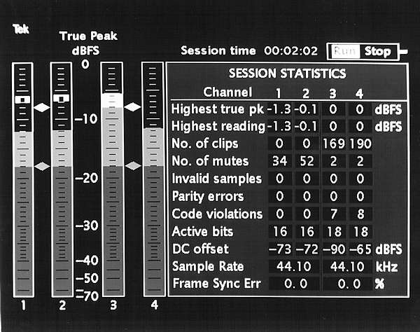
Figure 5. Session Screen accumulates statistics that characterize the quality of an audio program.
A powerful and unique capability of the 764 is its ability to compile the statistics associated with a digital audio passage. A display of the statistics is called the "Session Screen." As shown in Figure 5, the display of the statistics appears in lieu of the phase display.
One of the basic elements of the Session Screen is a display of time at the top of the screen. Depending upon the user selection, this can be VITC or LTC time or actual running time.
In addition to the display just mentioned, "time" also plays a central role in the logging operation of the 764. The logging mode (see Figure 6) time-stamps the occurrence of several important events.
Figure 6. First page of 764 logging report.
The following parameters are logged in the Session Screen display.
Highest True Peak retains the largest value indicated by the Peak Hold indicator.
Highest Bar Reading retains the largest value of bar graph level. In the event that the user selects either VU or PPM behavior for the bar graphs, the Highest Bar Reading will always be less than the Highest True Peak. Conversely, when True Peak behavior is selected for the bar graphs, then Highest True Peak and Highest Bar Reading will have the same value.
# Clips is a counter that accumulates the number of times the clip detector is triggered. Of course, the clip is only triggered when the sensitivity conditions (number of consecutive full scale samples) are satisfied.
# Mutes is a counter that accumulates the number of times the mute detector is triggered.
Table 1 System Error Messages
INPUT UNLOCKED | 764 not locked to incoming signal |
CODE ERR | Bi-phase coding violation has occurred |
PARITY ERR | Incoming subframe does not have even parity |
CRC ERROR | Channel Status Screen only |
LOW CONF | Indicates a marginal input signal on the interface |
V-BIT SET | Indicates validity bit is set high for the sample |
CHANNELS NOT SYNCHRONIZED | Indicates that Left/Right sample pairing is ambiguous |
Invalid Samples is a counter that accumulates the number of times a sample includes a high validity bit.
Parity Errors and Code Violations are counters that accumulate the number of times that each of these interface errors are detected.
Active Bits displays the number of bits in a sample that are active or changing states.
DC Offset displays the DC offset contained in the encoded audio. This capability enables fine-tuning of the DC offset characteristics of A/D converters.
Sample Rate displays the sample rate measured by the 764.
Session Screen can also be harnessed to accomplish some unique tasks:
Optimizing Dynamic Range
Two conflicting objectives must be balanced when producing digital audio material. First, engineers must avoid the full-scale clipping point. Typical practices allocate a certain amount of headroom, or amplitude margin, in doing so. An overly conservative headroom setting, however, wastes dynamic range and degrades the signal-to-noise ratio of the material. By monitoring the Highest True Peak and Highest Bar statistics, an engineer can observe how closely his mix approaches the clip point.
Quality Control Certificate
A hard copy of Session Screen can be produced on an ordinary serial printer connected to the rear-panel communication port. Thus, at the completion of a session, the accumulated statistics can accompany the work. Subsequent users of the piece, such as broadcasters, affiliates and postproduction engineers have a starting point at which to compare gain settings and error sources.
764 Logging Report
In addition to the hardcopy capability previously described, the 764 can produce logging reports on a number of important parameters. Logging information permits users to identify when certain important events have occurred.
Figure 6 illustrates this capability. The logging report contains a record of the peak audio levels stamped with the time of their occurrence. In addition, the locations of errors, clips, mutes and other events can be identified by their time of occurrence. The time stamp information employs the user selected VITC, LTC or running time displayed in the Session Screen.
Understanding Channel Status Data
The Tektronix 764 has special capability to recover and decode Channel Status data embedded in the serial data stream. Channel Status data is used to convey specific information about the audio data. It identifies the sample rate at which the audio was originally recorded, whether pre-emphasis was employed in the process, source and destination ID's and various important aspects.
Mismatches between the data transmitted by a device and the format expected by a downstream receiving device often prevent digital-to-digital data transfers. The 764 enables users to examine the channel status data in several different ways to confirm format and content.
Figure 7 illustrates the Channel Status Decode screen. The status block for Channel 1 is completely decoded to simple English language descriptions. Alternately, as shown in Figure 8, an adaptive cursor decodes the portion of the block displayed in bright video. Additional other displays are supported.

Figure 7. Typical decoded Channel Status data view.
The primary application for the Channel Status decoder capability is to examine the content and format in order to rule out channel status data as a possible cause of any digital-to-digital transfer problems.

Figure 8. Unique adaptive cursor decodes selected bits.
User Data
Similar displays of user data content are provided. However, only ASCII decoding is supported.
Application Examples
Figure 9 illustrates a critical audio A/D converter installation in a typical digital facility. In this case, the 764 serves a dual purpose. System setup and alignment can be quickly and easily checked with the 764. Once completed, the 764 serves as the main monitor for audio source material.

Figure 9. The 764 performs calibration and operational tasks in typical digital audio installations.
Technical adjustments supported by the 764 include ADC offset and gain adjustments. Using the Session Screen, DC offset may be adjusted to achieve the minimum practical DC offset value. Gain or lineup adjustments can be performed by switching to the audio level display and adjusting the ADC gain to achieve a suitable lineup or full-scale level. The expand and offset controls simplify this exercise.
Quick checks of phase, sample rate and other parameters can be made before returning the ADC station to service.
When returned to service, the 764 is employed to monitor system signals. Powerful level monitoring capabilities assure optimum use of system dynamic range. Accurate phase monitoring is assured by the combination of phase display and correlation meter. Confidence monitoring of the audio is as easily accomplished as connecting ordinary headphones. Finally, the logging and hardcopy capabilities can be harnessed to produce permanent records of signal and system performance statistics.
In Figure 10, the 764 is assigned to monitor various signals available on an AES router. In this case, a house Digital Audio Reference (DAR) such as that provided by a Tektronix SPG 422 or equivalent, is used as the system timing reference.

Figure 10. The 764's loopthrough inputs simplify complex monitoring tasks.
The DAR signal is used as the reference point against which the timing of all other signals are measured. By examining the Frame Error parameter on the Session Screen, operators can determine if signals are synchronized with the house digital timing signal or are "wild." Evaluations of critical level, phase and format comparisons can also be performed at the same time.
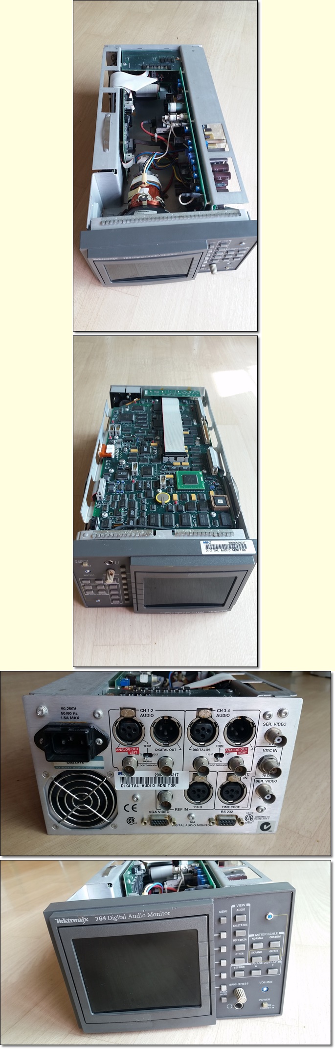
764 rear panel.


The Tek 764 is an extremely popular and practical digital audio monitor. It fits in any of the Tektronix 1700Fxx half-rack slide-in cases along with the Tek waveform monitors.
It sold for $5,000 - $7,000 new, and sells for about $300 used today.
If you are only monitoring two channels, the third and fourth channels can be set to look at the sum and difference of the first two channels.
It is an incredibly handy device for monitoring the real levels you're putting into or getting from a recording. It reads and logs many kinds of peak, PPM, average and VU levels, with enormous flexibility. It's easy to change the scales with dedicated front-panel buttons, and reads to fractions of a dB on the bar graphs.
Not shown in my studio-strobe photo above is that all the function lables above the buttons are backlit with LEDs when selected. The 764 is designed for use in dark studios.
You can set it to read the real (interpolated) levels of the actual audio signals represented by your digital data, or dumb it down to read only the (non-interpolated) digital sample values to match less-advanced meters.
Its headphone jack is loaded with plenty of level, and the volume control is fast, precise and tracks extremely well.
This 764 is unbeaten in being a very flexible real-time level and phase monitor, as well as identifying and logging peaks, clips and errors. It reads subchannel codes and has a Lissajous display, complete with auto level control. It also displays how many bits are active, up to 24.
It has a very high quality, 0.5% linear, 5,000 K monochrome raster-scanned CRT display. Tek paid extra for the linear CRTs so that the lines stayed straight, something a regular CRT would not have done
There is also a VGA output. Plug it into any VGA display, and you'll get the most glorious real-time color display you've ever seen.
Options
The 764 had two options available.
Option 02, analog audio line output, was extremely popular. It presents analog audio at the read male XLR connectors instead of the loop-through AES output. We at Tek developed this when customers demanded it after having to feed audio back into the rack from the headphone jack.
A less popular option is option 01, the ability to monitor digital audio embedded into a SMPTE 259M serial digital video signal.
Cases
The 764 is shipped without any sort of case. Your choices are:
Plain metal sleeve for use in custom installations: 1700F00
Dual Rack-Mount Case Room for two 764s): 1700F05.
Portable Case with Handle and Feet: 1700F02.
History
"764" comes from adding "4" to the model number of the prior Tek analog audio monitor from the 1980s, the Tek 760.
I was the Tektronix salesman in Hollywood, hired for the 764's introduction in 1995. I personally sold a zillion of these along with companion analog or digital video waveform monitors.
Professionals bought these by the pallet load, especially for use in monitoring television audio. The 764 lets inexperienced people see and automatically log if channels are muted, clipped or out of phase, leading to cancellation on mono TVs.
The only complaint we had was from very high-end mastering applications, where people spent hundreds of thousands of dollars making an NC25 (very, very quiet) studio, and discovered that the 764 has a cooling fan! These folks then mounted the 764 in the machine room and brought a remote VGA monitor back into the studio. Others mounted a fan remotely and plumbed a hose. Tek secret: being so crazy about reliability, we ran an 764 in our lab for a few years in our lab without a fan to see what would happen, and it ran fine. Don't do this today, because while Tek services the 764 in 2012, they aren't making any more, so be careful with what you have.
The only design flaw, which was obvious when I sold them new and loaned my sample out, is that the front-panel controls use plastic shafts, so the knobs break off. Tek can still replace these in 2012.
The 768
The 764 was replaced in the 2000s by the Tek AMM 768. Tek made and showed secret prototypes of an eight-channel version of the 764 with a color LCD in the early 2000s, but Tek decided not to make it since it cost as much as two 764s, so it wasn't worth it. The Tek AMM 768 came out after I left Tek in 2004.